Abstract
This paper presents for the first time a quad-core oscillator based on a very compact interstacked transformer that tightly couples the four cores without oscillation mode ambiguity thanks to its strong magnetic coupling factor. As a proof of concept, a 19.125 GHz oscillator for a narrowband 77 GHz radar system was designed in 28 nm fully depleted silicon-on-insulator CMOS technology with a general purpose back-end-of-line. The soundness of the proposed quad-core oscillator topology is demonstrated by comparison with state-of-the-art quad-core solutions, highlighting a significant advantage in terms of area occupation and power consumption. The proposed topology can be profitably exploited in several RF/mm-wave applications, such as radar and wireless communication systems.
Keywords: CMOS integrated circuits; fully depleted silicon on insulator; interleaved transformers; interstacked transformers; phase noise; power consumption; quad-core oscillator; stacked transformers
1. Introduction
Radio frequency (RF) and mm-wave applications, such as radar (radio detecting and ranging) and 5G, require the generation of frequency-modulated signals that are typically realized by a voltage-controlled oscillator (VCO), driven by a modulator, inside a phaselocked-loop (PLL). The VCO is the key block, especially in applications needing stringent phase noise performance. For instance, accuracy and resolution of a radar sensor are strictly related to the phase noise, thus a low-phase-noise oscillator is mandatory to achieve the highest possible target discrimination [1,2]. In this context, LC-resonant VCOs are highly preferred at the cost of a large silicon area consumption, mainly due to the tank inductor [3,4,5,6,7,8]. Traditionally, RF/mm-wave ICs are implemented in BiCMOS or CMOS technologies [9,10,11,12,13,14]. Despite several advantages of BiCMOS over CMOS in terms of noise (i.e., lower flicker noise corners), thicker back-end-of-line (BEOL) [15], higher transistor breakdown voltage (BV), and lower transconductance, gm, at a given current level, CMOS is becoming the reference process since it is highly suitable for system-on-chip (SoC) integration, which is pursued by microelectronic industries to reduce chip cost, power consumption, and area occupation [16,17]. Unfortunately, the transition from BiCMOS to CMOS requires proper topologies and design approaches for almost all main RF/mm-wave front end blocks. In the last few years, several techniques have been developed to minimize phase noise and improve overall performance of CMOS VCOs. Specifically, multi-core techniques, which consist of coupling multiple in-phase oscillators, are theoretically powerful solutions for CMOS low-phase-noise VCO design. Indeed, the phase noise of multi-core oscillators theoretically decreases by 10 × log (N), where N is the number of cores [18,19,20,21]. However, existing implementations achieved significant phase noise reduction at the expense of power consumption and silicon area. These two parameters are often the limit to the adoption of a solution in a commercial product. Current state-of-the-art solutions to mitigate this problem involve the use of stacked inductors to couple the cores [22]. While this allows reducing the area occupation, it is still not an optimal solution for quad-core oscillators, due to the intrinsic asymmetry between the cores and the need to have two passive structures.
This work presents a novel solution based on an interstacked transformer topology, which is highly suitable for a quad-core implementation of a VCO and allows significantly reducing both area occupation and power consumption. The paper is organized as follows. A brief review of the multi-core technique is provided in Section 2 to highlight benefits and drawbacks of state-of-the-art solutions, while Section 3 introduces the interstacked topology in comparison with traditional configurations. Section 4 and Section 5 are focused on the design of an interstacked transformer and the quad-core oscillator, respectively. Finally, conclusions are drawn in Section 6.
2. Multi-Core Oscillator Review
The best design strategy for phase noise minimization of LC-resonant VCOs is to use a low inductance value, L, while maintaining a sufficiently high tank quality factor, QT (i.e., minimize the L/QT ratio). However, low inductance values are related to higher losses in the tank, which means that optimizing the phase noise performance could be in contrast with the power consumption. Therefore, the L/QT ratio minimization must be pursued by a tradeoff between the inductance value, L, and the resulting tank quality factor, QT. Unfortunately, two issues hinder the above design strategy in practical implementations. First, low inductance coils are highly sensitive to layout parasitics. Second, inductance decrease would imply a consequent increment of the overall required capacitance, which would intrinsically exhibit lower-quality factor, QC, especially at mm-wave frequencies, with a resulting QT degradation. Given the integration technology, these constraints set a limit to the minimum phase noise that a single oscillator can achieve.
The multi-core technique allows overcoming the above-described limitations and pursuing L/QT ratio minimization. The main idea is to couple multiple oscillators (i.e., cores) together by connecting them through a generic impedance network to put their output voltages in phase. The coupling network can be resistive, capacitive, or inductive. In general, a complex impedance network can be realized. A theoretical analysis of different types of coupling and their impact on oscillator performance is available in [20]. Ideally, at steady state, no current flows through the coupling network, and all outputs are virtually “shorted”. To achieve a robust coupling design, the coupling impedance must be low-Q, and as low as possible to guarantee enough suppression of undesired oscillation modes and a strong coupling between the cores, respectively.
It can be easily demonstrated that the phase noise ideally decreases by a factor of two by coupling two identical cores. In general, coupling N identical cores allows ideally reducing the phase noise by a factor N. Equivalently, it can be said that coupling N cores lowers the phase noise of 10∙log (N) dBc/Hz. Unfortunately, at the same time, the multi-core technique causes an increment by factor N of both power consumption and silicon area occupation, compared to a single oscillator core, if special arrangements are not adopted. Moreover, circuit and layout complexities increase with the number of coupled cores, which can degrade the phase noise benefit due to parasitics. Therefore, a good tradeoff between complexity and phase noise reduction is represented by the quad-core solutions.
3. Interstacked Transformers
At mm-wave frequencies, integrated transformers suffer from very poor magnetic coupling factor, k, due to the low coil inductance values typically adopted (e.g., 50–150 pH). Moreover, interconnection parasitics further limit the magnetic coupling since their weight can represent up to 30% of the overall inductance. Integrated transformers are usually implemented by adopting conventional configurations, such as interleaved or stacked spirals as shown in Figure 1a and Figure 1b,c, respectively, according to specific performance requirements and operating frequencies [23,24,25,26,27]. Traditional configurations present pros and cons. Interleaved transformers take advantage of multilayer symmetric spirals to maximize both primary and secondary Q-factors, but do not achieve high k. On the other hand, stacked transformers are area efficient and have better k, while losing the electrical symmetry between coils that is often mandatory in some circuits. Unfortunately, stacked transformers suffer greatly from magnetic coupling degradation at mm-wave frequencies (i.e., when sub-nH inductance values are used).

Figure 1. Transformer configurations: (a) Interleaved, (b) Stacked, (c) Folded stacked, (d) Interstacked.
The implementation of an area-efficient quad-core oscillator requires the availability of a high-k symmetric transformer configuration, as with the interstacked one shown in Figure 1d [28]. The interstacked transformer takes advantage of mixed interleaved/stacked windings, which improves the magnetic coupling between primary and secondary coils, still preserving geometrical/electrical symmetry and easiness of input/output connections. Specifically, it consists of two spirals of different metal layers, using complementary structures for primary and secondary windings. Indeed, the outer (inner) spiral of the primary winding is stacked to the outer (inner) spiral of the secondary winding and interleaved with the inner (outer) spiral of the secondary winding at the same time, thus exploiting both interleaved and stacked magnetic couplings. The interstacked transformer has several benefits at mm-wave frequencies. The improvement of magnetic coupling becomes significant in mm-wave optimized technologies that use thicker oxides between upper metal layers. In this case, the advantage of stacked coils is highly reduced and the interstacked structure can improve the overall magnetic coupling by more than 10%, especially when close inter-metal spacing is used [28]. Another important benefit of the interstacked structure is the electrical/geometrical symmetry, which provides similar performance for primary and secondary windings in terms of inductance and Q-factor.
Despite the advantages, the interstacked configuration has been rarely used due to higher design complexity compared to standard transformers. The interstacked transformer has been mainly exploited in improving the efficiency of the output matching network of a 77 GHz power amplifier [29].
As a first but effective design of an interstacked transformer, a simple lumped model has been proposed in [30]. For the sake of completeness, the model schematic is reported in Figure 2, along with main design equations and geometrical parameters. It is made up of two π-like networks, each for the primary and the secondary windings. The primary (secondary) winding is composed of a top MT (bottom MB) outer spiral shunted to a bottom MB (top MT) inner spiral. As a consequence, the total inductance of the primary (secondary) transformer winding can be modeled by the shunt of two inductances, LMTP and LMBP (LMTS and LMBS), corresponding to the outer (inner) and inner (outer) spirals. To consider the positive mutual inductance between the spirals of the same winding, additional inductances, Lm, are also added in series. The low-frequency inductance values of outer (LOUT) and inner (LIN) spirals can be calculated by using the current sheet expression for octagonal coils (a) [31], where davg is the average diameter and ρ is the fill factor calculated according to equations (d) and (e). The series contribution, Lm, is drawn from the mutual coupling between spirals (by means of the magnetic coupling factor km). The model uses two series resistances in both primary and secondary windings corresponding to the outer and inner metal coils. Their frequency-dependent values are calculated using expression (b), where ROUT,IN and RDCOUT,IN are the overall and dc series resistances of both outer and inner spirals, respectively, and f is the frequency (expressed in GHz). RDC OUT,IN can be calculated using the geometrical parameters of the spiral and its metal sheet resistance.
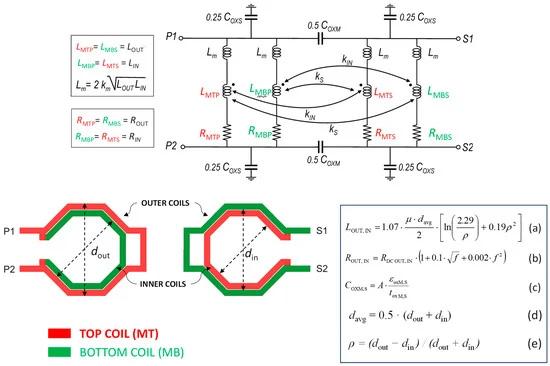
Figure 2. Physics-based scalable lumped model for interstacked transformers with related equations.
Magnetic coupling effects consist of two phenomena:
-The stacked coupling between outer (inner) spirals built in the top metal in primary and secondary windings, respectively, modeled by including a magnetic coupling factor, kS, between LMTP and LMBS (and between LMBP and LMTS).
-The interleaved magnetic coupling between outer and inner spirals built in the same metal layer and belonging to different windings, modeled by adding a magnetic coupling factor, kIN, between LMTP and LMTS (and between LMBP and LMBS).
Coupling factors km, kS,, and kIN could be drawn from EM simulations of open-air coupled spirals (i.e., without the silicon substrate beneath) separated by silicon dioxide of proper thickness, as proposed in [30]. Finally, capacitive effects are taken into account by means of the port-to-port inter-metal (COXM) and port-to-substrate (COXS) capacitances that mainly arise from the area contributions. They are calculated by using the expression (c), where εoxM,S and toxM,S are the oxide dielectric constant and thickness, respectively, and A is the area of the spirals. The model geometrical scalability allows using it as a simple but effective tool for the starting design of interstacked coils, while exploiting EM simulations for final accurate modeling.
4. Design of an Interstacked Four-Port Transformer
A reduction in the power consumption of VCOs can mainly be achieved by increasing the tank inductance value. This generally leads to designing larger and larger inductors, consequently increasing area occupation, and hindering the adoption of such solutions in commercial products. By adopting a transformer-based solution, it is possible to exploit the magnetic coupling between the coils to obtain large inductance values without impacting the area. Ideally, the greater the coupling factor, k, between the coils, the greater the area reduction and the better the coupling between the cores. Interstacked transformers—which exploit both the interleaved and stacked magnetic coupling between the coils—have proven to be a good solution for achieving high k values [28,29,30]. Compared to commonly used stacked transformers, they provide comparable or even higher k-factors and are intrinsically symmetrical. It should be noted that it is hard to find already-available solutions for interstacked four-port transformers. The main challenge of such a structure is to design a layout such that four coils—one for each core—can be interstacked by using only two metal layers, which is something that cannot be achieved by a simple stacked-transformer solution.
A 28 nm fully depleted silicon-on-insulator (FDSOI) CMOS technology is used in this work. It provides a BEOL having a thicker aluminum upper layer (ALUCAP) and two thinner copper lower layers, used in shunt—for the proposed transformer design—to minimize the difference in thickness between lower and upper metal layers. A simplified BEOL of the adopted CMOS technology is shown in Figure 3.
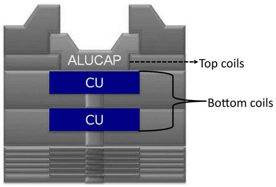
Figure 3. BEOL of the adopted 28 nm CMOS technology with eight metal layers [15,32].
The novel interstacked four-port transformer implementation is shown in Figure 4a. No patterned ground shield (PGS) was implemented to improve the self-resonance frequency (SRF) [33,34]. To better understand the geometry of the transformer, Figure 4b depicts the single coil which the whole structure is composed of. This “squashed” coil is obtained by the composition of two octagonal coils having different diameters, as shown in Figure 4c. Four of these coils are overlapped—each rotated by 90 degrees with respect to each other—to build the four-port structure of Figure 4a. An important aspect to mention is that there is a geometrical constraint that correlates the width of the coils and the inner diameter of the structure. For a given inner diameter, din, and for this given technology, the maximum coil width, wmax, that cannot be exceeded is given by the following expression.

Figure 4. (a) Interstacked four-port transformer, (b) one of the four “squashed” coils used to build the interstacked transformer, (c) two octagons—the red dashed–dotted line—with different diameters are overlapped to the coil to highlight its geometry.
If a greater coil width was chosen, it would be impossible to guarantee the minimum spacing between the metal traces belonging to the same layer. Equation (1) suggests that there is a tradeoff between the coil width—which is proportional to the Q-factor—and how low the inductance can be. A coil width, w, of 11 µm was chosen for the proposed design, leading to an inner diameter of 65 µm. Table 1 reports the geometric data of the proposed transformer. A single coil, such as the one depicted in Figure 4b and having the size shown in Table 1, has an inductance of 146 pH and a Q-factor of 22 at 19.125 GHz. However, thanks to the magnetic coupling between the coils of the interstacked transformer, the equivalent inductance seen by each core is much higher than the one of a single coil, while keeping the same area occupation. Figure 5 shows the magnetic coupling factors between the four coils of the interstacked transformer. It is worth noting that slightly higher values are found for the magnetic coupling factors between orthogonal coils, given a slightly greater overlapping between them, as shown in Figure 6a,b. However, at the operating frequency of 19.125 GHz, k is always higher than 0.5; that is a very good result. Indeed, very small (symmetric) coils are used, which further confirms the advantages of the adopted interstacked structure.
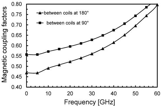
Figure 5. Magnetic coupling factors between the coils of the interstacked transformers.

Figure 6. View of the overlapping between (a) opposite coils (180°) and (b) orthogonal coils (90°).
Table 1. Geometric parameters of the proposed interstacked transformer.
Figure 7 reports the equivalent inductance seen by each port and its corresponding Q-factor. A value of 363 pH at 19.125 GHz is achieved. Its corresponding Q-factor at 19.125 GHz is as high as 21. The SRF is 69 GHz. It is worth mentioning that by coupling the four cores, the tank impedance of each one of them is in shunt with the others. The total effective tank impedance is then a quarter of the one seen by each port. That means that the total effective inductance at 19.125 GHz is as low as 90.8 pH.
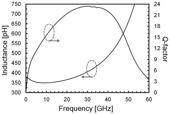
Figure 7. Equivalent inductance and Q-factor seen by each port of the interstacked transformer.
Since the interstacked transformer has four ports, four different oscillation modes could be triggered at startup. A good transformer design allows selecting only the desired mode and suppressing the others. This is achieved if the inductance has a high Q-factor at the desired oscillation mode, while being low at the undesired ones. A further simulation was then carried out to find all four possible oscillation modes with relative Q-factor. The results are reported in Table 2. The proposed solution is quite robust in this regard. Only the desired mode (mode 1) has a high Q, because of the constructive magnetic coupling between the coils. All other modes—which are found at higher frequencies—have small Q-factors due to the destructive coupling. Oscillation occurs at the desired mode at the startup. This analysis suggests that a strong magnetic coupling between the coils—such as the one provided by an interstacked transformer—carries the advantage of suppressing all the undesired modes, leading to no mode ambiguity, which is one of the most critical issues of multi-core oscillators.
Table 2. Oscillation modes for the interstacked transformer and corresponding inductance and Q-factor values.

5. Quad-Core VCO Design Based on an Interstacked Transformer
A quad-core VCO to be used in a narrowband 77 GHz CMOS radar system for automotive applications [15] was designed in 28 nm fully depleted silicon on insulator (FD-SOI) CMOS technology by STMicroelectronics, exploiting the four-port interstacked transformer shown in Section 4. The technology provides low-VT transistors, which exhibit a transition frequency, fT, up to 270 GHz [32]. The process features a general purpose BEOL with eight copper layers and a top aluminum one [15], as shown in Figure 3.
Figure 8 reports a complete schematic of the quad-core VCO. The operating frequency of the VCO was set at 19.125 GHz to be later multiplied by four along the radar chain. A complementary cross-coupled oscillator was used since the supply cannot be fed through a center tap in the transformer. Moreover, no tail current was used, to maximize the output voltage swing. A supply voltage, VDD, of 1.2 V was chosen. The transconductance, gm, of the cross-coupled transistors was set at three times the minimum required by the Barkhausen criterion to obtain a robust startup and to achieve an oscillation amplitude of about 1 V. For the PMOS and the NMOS transistors, 63 nm and 90 nm transistors’ channel lengths, respectively, were used to minimize the transistors’ flicker and thermal noise, without excessively increasing their parasitic capacitances. The ratio ()N
was chosen to set the dc output voltage at DD/2
. Finally, a differential varactor provides a 5.5% tuning range (around 1 GHz), covering the operating frequency range, the temperature variations, and part of the process variations. To be able to fully cover process variations, a 3-bit switched capacitor bank is exploited, achieving a total of 20% tuning range. A minimum overlap of 460 MHz between the bands is guaranteed.
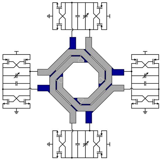
Figure 8. Schematic of the proposed quad-core VCO with interstacked four-port transformer.
The achieved performance, along with a comparison with the state-of-the-art quad-core solutions, is reported in Table 3. The expressions of the figures of merit (FoMs) used for the comparison are the following [20,21,22,35]:
FoMT=FoM−20log10(TR10),(3)
FoMA=FoM+10log10(Areamm2),
(4)where PN is the phase noise, f0 is the oscillation frequency, Δf is the offset frequency from the carrier at which phase noise is measured, PDC,mW is the dc power consumption expressed in mW, TR is the frequency tuning range, and Areamm2 is the area consumption expressed in mm2. The oscillator phase noise is shown in Figure 9.
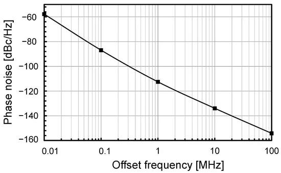
Figure 9. Interstacked VCO phase noise at 1 MHz offset from the carrier.
Table 3. Performance comparison with the state-of-the-art quad-core VCOs.
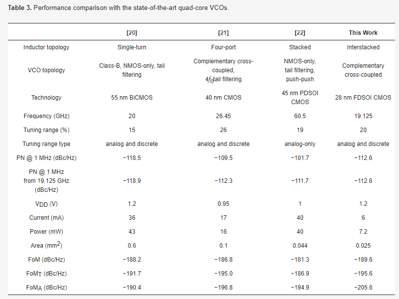
The proposed interstacked transformer quad-core VCO design exhibits a low phase noise while having minimum power consumption and area occupation. It achieves a 24× area and 6× power consumption reduction with respect to [20]. It has 1 dB lower phase noise than the stacked-transformer-based solution [22], along with a 7× reduction in power consumption and a 43% reduction in area occupation.
6. Conclusions
A quad-core VCO, exploiting an interstacked four-port transformer to magnetically couple the four cores, has been proposed. As expected, area occupation and power consumption are extremely low, while keeping the phase noise at a low level. This allows its use in commercial products. The comparison versus state-of-the-art quad-core VCOs further confirms the strength of the proposed solution. Although the focus of the present work is 77 GHz radar, the field of application is wide and includes all modern wireless communication systems.


